
Ever wonder why a white color-looking powder of feldspar can turn out the black or dull color after firing? Ceramics are none less than chemistry magics of forming bonds and reacting with various other minerals causing it to change its appearance. (Sometimes more Drastic changes)
To solve this mystery, I am on a mission to share my learnings throughout this journey. This series will help you understand the glazing part of ceramics material and help you know more about various minerals.
There are various materials that causes colour changes of material but today we will study the most common affecting colouring oxides : Iron and Titanium.
While in search of the reason behind the color change, I found the research paper by Ewa Lewicka and Anita Trenczek-Zajac studying Investigations of Feldspar-Quartz Raw Materials After Firing: Effect of Various Na2O/K2O Ratio and Synthetic Pigments Addition
This paper helped me to understand the color reaction in feldspar.
So, This is my understanding from the research paper I found:
Thinks you should know before reading this article:
- Understanding of how molecular bonding works.
- Difference between Fe2+ and Fe3+ Ions: The difference between Fe2+ and Fe3+ is that the Fe2+ has a pale green color and turns violet when water is added. While Fe3+ forms blood-red when it reacts with thiocyanate ions. Fe2+ has paramagnetic properties (weak magnet) whereas Fe3+ has diamagnetic properties(magnetise at 180 degree).
- D-D Transition
Experiment
To answer this question, let me start with explaining to you a simple experiment which includes a sample of :
Synthetic coloring agent:
1) Fe2O3: Hematite
2) TiO2: Rutile
These are some of the most coloring oxide agents found in nature. Note: This experiment uses synthetic FE2O3, which has a content value of 99%, and TIO2 as 99% content purity.
In nature, you can find feldspar in a variety of colors such as white, grey, yellow, pink.
Equipments and Process:
To test this experiment, you can use various techniques such as:
- Chemical analysis: Test to identify the content in the powdered form of raw material.
- Xrf: X-ray diffraction technique helping to understand content present in raw and after fired state. It uses a beam of X-ray that hits electrons of elements which gets excited and released from atomic orbital. This energy then it can be tracked to identify the elements present in the sample.
- Mössbauer spectroscopy: Technique uses gamma-ray at varying velocity to identify Fe(Iron) valance state and type of co-ordination Number.
- UV-Vis-NIR spectrophotometry: Double-beam spectrophotometer equipped with a dedicated 150-mm integrating sphere to perform the total absorbance measurements.
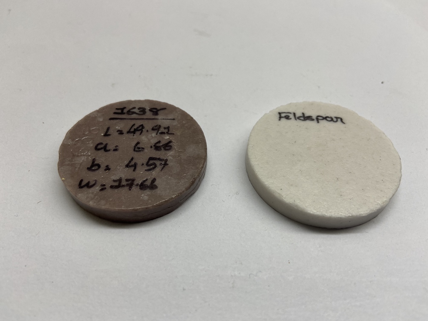
- Chromaticity measurement: also known as L A B C H channel test for color and accuracy. L* refers to darkness-brightness (0–100), a* to the red (a* > 0) or green (a* < 0), and b* to yellow (b* > 0) or blue (b* < 0).
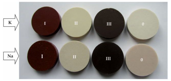
Sample Used In this Experiment
Sample 0: No addition of synthetic pigments
Sample 1: FE2O3 – Increase of 1.5 % by content
Sample 2: TiO2 – Increase of 0.5 % in content
Sample 3: TiO2 (Increase of 0.5 % in content) + Fe2O3 (Increase of 1.5 % by content)
Adding Colouring agent in three different variations by weight % added to standard sample:
Table : Reference to sample contents

Steps to Prepare sample:
- Use a 20 g powdered form sample.
- Add few drops of water and press into pellets size 40.4 mm
- Disk and thickness of 10 mm.
- Use hydraulic pressure of 100 kN while pressing.
- Using the Quick Firing technique as in ceramics, fire the sample. In this case, 51 min cycle in an electric furnace with a 1200 degree Celcius is used to melt. It took 22 mins to reach 1200, and 6 mins holding time for firing sample and then rapidly cooled off to 95 degrees Celcius in 23 mins.
- After firing these samples, you can check this use various techniques as mentioned.
- The content of Potash Feldspar and Soda Feldspar:
XRD Analysis
For Soda Feldspar:
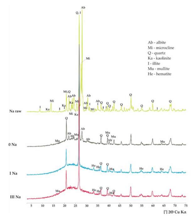
1) Raw Sample: the presence of albite, quartz, and Microline.
2) After firing results:
Sample 0: diffraction into glassy phase(from 15-40 degrees) presenting characteristics of the amorphous hump. Parts of quartz and albite were not completely melted.
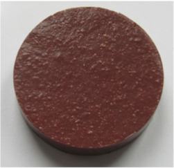
Sample I: No Microcline peak. 4 Weak Fe(Hematite peaks), and larger humps in amorphous phase at the expense of albite.
Sample 2: No View.
Sample 3: No Microcline peak. 2 Weak Fe(Hematite peaks), and larger humps in amorphous phase at the expense of albite.
Results: Sample 1 and 3 had more extensive iron oxide content as it may be due to thermal decomposition of albite.
For Potash Feldspar:
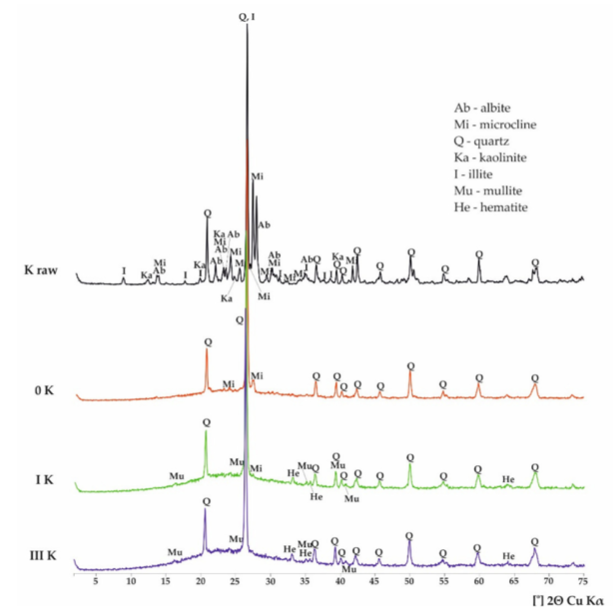
1) Raw Sample: result shows the presence of Quartz, Microcline (KAlSi3O8).
2) After firing:
Sample 0: the disappearance of most peaks, especially of illite, kaolinite, and albite except quartz and some microclines.
Sample I: the decay of microcline reflection, a small peak of mullite and hematite, raise hump in the amorphous phase. We see a drastic change in intensity after firing in most materials when compare with the raw state.
Sample 2: No View.
Sample 3: the decay of microcline reflection, a small peak of mullite and hematite, raise hump in the amorphous phase
Result:
Smaller humps for the amorphous phase when compared with silica. This causes a high melting temperature for smaller humps. When we see the melting process, soda feldspar melts congruently, and potash feldspar melts incongruently. Hence potash feldspar has a melting point around 1150 ± 20 ◦C. forming the liquid phase containing leucite and silica, and soda feldspar have 1118 ± 3 ◦C.
Also, potash feldspar has high viscosity than soda feldspar. Thus, at high temperatures, the glassy phase forms slower and in smaller quantities.
When it comes to sodium feldspars, they turn into the liquid phase faster, and secondary mullite crystalizes earlier and more easily. Hence melting more quickly can also be troublesome as it causes bubbles to appear on the surface. When compared to K feldspar, no surface irregularities are found.
The peaks of rutile or other titanium phases were not identified. This was probably due to their concentration below the detection limit of the XRD method.
Mössbauer Spectroscopy
Test to identify valency and co-ordination number of Fe Ions.
Takes 3 step identification technique:
1) Isomer shift: The isomeric shift (also called isomer shift) is the shift on atomic spectral lines and gamma spectral lines, which occurs due to the replacement of one nuclear isomer by another. The isomer shift is useful for determining oxidation state, valency states, electron shielding, and the electron-drawing power of electronegative groups
2) quadrupole splitting: In this case, an asymmetrical electric field (produced by an asymmetric electronic charge distribution or ligand arrangement) splits the nuclear energy levels. The quadrupole splitting can be used for determining oxidation state, spin state, site symmetry, and the structure of ligands.
3) magnetic field: Magnetic hyperfine splitting is a result of the interaction between the nucleus and any surrounding magnetic field, as described by the Zeeman Effect. In ferromagnetic materials, including many iron compounds, the natural internal magnetic fields are quite strong, and their effects dominate the spectra.
Reference: Wiki
You can check table below for sample that includes iron (Type 1 and Type 3) for both soda and potash feldspar.

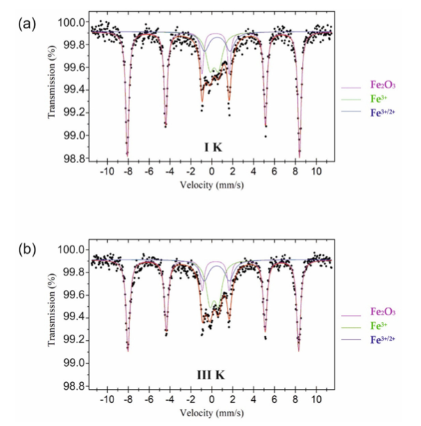
All the values suggest a strong presence of synthetic hematite presence in the sample. This leads to iron ions released from the lattice of other minerals at high temperatures.
The presence of Fe3+/2+ may be a result of the reduction of some Fe3+ ions to Fe2+ due to their substitution by Ti4+.
It’s worth noting that quadruple splittings have caused K-1 and K-3 sample changes as titanium has played a role, but soda samples remain the same for those processes. However, based on the results of Mössbauer spectroscopy measurements, neither the titanium role nor titanium and iron interaction in the case of samples marked III of both varieties of raw materials can be cleared.
UV-Vis-NIR Absorbance Spectra
It is a simple test to measure light wavelength that determines the color and checks in Non-visible regions such as IR and UV spectrum.
The machine will measure wavelengths from 200 to 2200 nm for all samples.
The plotted graph shows the color of all samples.
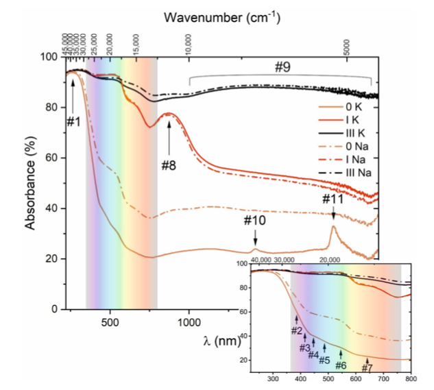
Visible range:
From this graph, we can clearly see that small Iron content in raw material has clearly shown the color difference in samples 1 and 3 in both types of feldspars.
There is also the presence of series of small bands of Fe3+ in this visible spectrum d-d transition. Marked at 384 (#2), 413 (#3), 448 (#4), 487 (#5), 545 (#6), and 642 nm (#7). Fe ions in tetrahedral form were found at #2 to #4 mark and octahedral marked at #5 and #6.
UV Range:
Mark 1 in the graph shows clear absorption at 262 nm, maybe because of ligand-to-metal charge transfer. This means transition might be taking place between O2- and Fe3+ ions.
IR Range:
At mark #8, absorption is observed in this spectrum consisting of Alpha-Fe2O3, and another weak absorption is observed starting at 100 to 2150 nm marked at #9. This indicated the presence of Fe2+ ions as overlapping is clearly seen in the graph. The reason for overlap is probably Jahn-Teller distortion of the octahedrally coordinated iron ions.
Comparing Samples with 0-K and 0-N:
1) 1-K and 1-Na have increased their absorption in the UV region and shifted towards a longer wavelength of 390 nm in the visible range. This can occur due to the presence of Fe3+ ions. Redshifting of color indicated charge transfer between fe3+ and O2- ions. More absorption is seen at 550 nm due to the magnetic interaction of Fe3+ ions. Further, shifting of the absorption band is seen towards a longer wavelength due to the d-d transition. Hence we see a change in electronic structure due to the presence of iron.
2) 3K and 3Na results in a very high absorption rate with an increase of 82% between 220 nm and 2200 nm. Redshift band still shows up even though Fe3+ is less. At 860 nm, we see weak absorption when compared with 1-k and 1-Na samples. The broad spectral band near IR assigned to Fe2+ ions is more distinct. Note that the IR range is also clearly seen with a high absorption rate compared to all other samples related to Fe2+ ions.
It should also be noted that the broad spectral band in the near IR assigned to Fe2+ ions is more distinct than that observed in other spectra.
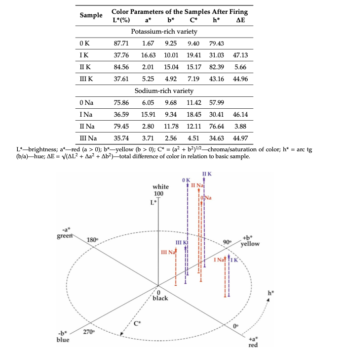
Chromaticity analysis
The lower absorption rate of the sample indicates a higher whiteness and vice versa.
L* refers to darkness-brightness (0–100), a* to the red (a* > 0) or green (a* < 0), and b* to yellow (b* > 0) or blue (b* < 0).
Sample 0 of K-Feldspar: Has the lowest absorption rate of all samples, and hence it’s the brightest one. L value 87.71 % as shown
Mixing of Fe2O3 results in a Decrease of Brightness to 37.76% () and 36.59% in 1K and 1 Na. Because of the breakdown of iron at High Temperature with the formation of Fe2O3 and Fe3+ ions. Hence, strong absorption at 570 nm caused dark brown color due to d-d electronic transitions in Fe3+ ions and plus Fe3+–Fe3+ pair electron excitation in hematite(Fe2O3).
Sample with TiO2 and Fe2O3 content shows further absorption is mainly caused by iron ions following the charge transfer between Fe and Ti.
Interesting facts:
“It is well known that in silicate melts, iron may occur in both oxidation states, as Fe2+ and Fe3+ ions, of which Fe2+ acts as a network modifier (flux) and thereby lowers the melting point and viscosity. ”
Final Discussion:
K is larger than the Na atom; hence, there is less space to correspond to lower Fe-O bonding. It is found that CN(Co-ordination) number is higher for Na(CN=5) than K (CN = 4). Higher the Co-ordination Number, higher the bonds between atoms, higher the strength between bonds, higher splitting energy of 3d levels, hence higher absorption of light causing it to change the appearance of sample.
Conclusion:
– Presence of Iron and TiO2 are not only the main reason for the change in the appearance of material but also their valence state and coordination number as well as chemical characteristics of the melt itself. Found through spectroscopic methods and chromaticity measurements.
– Mössbauer and UV-Vis-NIR analyses shows presence of α-Fe2O3, Fe3+, Fe2+ and Fe3+/2+ ions.
– Ligand-to-metal charge transfer between (O2−) and iron (Fe3+) resulting in absorption of light from UV range into Visible range. Hence had a change in appearance. Further invisible spectrums changes were also seen in this experiment.
– Mixing Fe2O3 pigment maximized the absorption range in the visible region associated with increased content of Fe3+ ions as well as in the appearance of the firm and well-defined bands assigned to hematite.
– Fe2O3 and TiO2 has widened the strong absorption range in the visible and near-IR regions
– Weak absorption band attributed to α-Fe2O3 combined with the confirmed presence of Fe3+ ions may suggest successful doping of iron into TiO2.
– Reduction of Bond length and strength can also be helpful to reduce appearance change after firing. This occurs in a large atom of K, which reduces the bond strength and length of the Fe – O bond. So we can clearly see the difference in 0-K and 0-Na sample color variation through the L value.
– Darkest color was observed in TiO2 and Fe2O3 samples, resulting from charge transfer between Fe and Ti atoms. Hence absorbed maximum light in the visible spectrum.
Further, we can say that to make a bright glaze ceramic material, you can achieve it by controlling the chemical composition of Feldspar raw material, and knowing the reduction and oxidation state of the Iron atom can help you determine the color.
MY THOUGHTS:
- Lesser the Fe content the safer you are while creating a bright colour glaze.
- TiO2 acts as whitening agent in glaze so this won’t be issue if you are required to make a white glaze
- Make sure there is low iron and TiO2 content in sample else it will turn it into black colour sample due to Ti-Fe Strong bonding.

